Level Crossing Battery Monitoring: A Practical Guide
Batteries underpin almost every safety function at a level crossing — the warning lamps, the control logic, the data logger, and whatever additional equipment is fitted to the site. They are also the single most common source of unplanned site visits. This guide covers what battery banks a typical crossing carries, how to monitor them remotely, and what alarms to raise to catch a fault before it cascades.
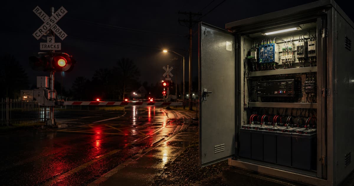
What batteries does a level crossing have?
Every crossing is a bit different, but two battery banks are effectively always present — and additional banks are added on top wherever a piece of equipment warrants its own supply. Counting and identifying them properly during commissioning is the first step toward meaningful monitoring, because every bank needs its own measurement, its own setpoints, and its own alarm path.
| Bank | Notes |
|---|---|
| Signalling battery | Always present. Powers the warning lamps, bells, flasher driver, and control logic. |
| Data logger battery | Always present. Deliberately isolated from the signalling supply so the monitoring system survives a signalling-side power event long enough to report it. |
| Additional banks | Variable by site — added wherever equipment warrants its own supply. Common examples: booms or pedestrian gates, advance warning lights on the road approach, axle counters, predictors, and interlocking processors. |
The data logger bank is the one to get right. A monitoring system that loses its own power when the site loses its is a monitoring system that goes silent at the exact moment the operator needs to hear from it — so the logger battery is always wired and monitored as a first-class bank in its own right, not as an afterthought sharing the signalling supply.
Common causes of battery faults
- Mains supply loss — extended discharge once the charger has nothing to draw from
- Charger failure — output stage failed, internal fuse open, no longer floating the battery
- Insufficient solar charging — daily charge energy falling short of daily load. Causes include extended bad weather, panel soiling (dust, bird droppings), partial shading from vegetation growth, panel degradation with age, MPPT controller misconfiguration, or an ageing bank whose charge acceptance has dropped. Gradual rather than binary — no single relay drops, but the bank trends down over days.
- Cell ageing — capacity loss with cycle count and elevated cabinet temperature
- Sulfation or dry-out — VRLA cells left at low state of charge or run hot for extended periods
- Wiring and connection faults — corroded terminals, loose links, broken fuse holders
- Overcharge — charger setpoint drift driving the bank above its safe float window
How to measure battery voltage remotely
Battery voltage is typically brought into the logic application in one of two ways:
- Resistor divider — scales the battery voltage down into the analogue input range of the controller. Cheap, reliable, but shares a common reference with the rest of the input card.
- Signal isolator — galvanically isolates the battery from the input, eliminating earth-loop concerns and protecting the controller from supply transients. Preferred where multiple banks at different reference voltages are measured by the same controller.
Either way, each measured bank is compared against high and low setpoints to raise Battery Low Voltage and Battery High Voltage alarms. Because sites around a network run a mix of 12 V, 24 V, 48 V and sometimes 110 V signalling supplies, the configuration should be organised in two tiers:
- Standard threshold templates per nominal voltage — one template each for 12 V, 24 V, 48 V, 110 V, holding the float, high, and low setpoints appropriate for that nominal. When a new bank is commissioned, the engineer picks the template that matches the nominal voltage and the defaults apply. This is what most banks need, most of the time.
- Per-bank override — any individual bank can override the template values where the installation calls for it (an unusual battery chemistry, a different float regime, a charger setpoint outside the standard window). The override sits on top of the template; the rest of the network configuration is unaffected.
The point of the two tiers is to keep the common case trivial — pick a template, done — without losing the ability to handle the one bank on the network that does not conform. A flat per-bank-only configuration drowns the engineer in setpoints; a template-only configuration breaks the moment a non-standard site appears.
Detecting charger and mains faults
Voltage monitoring alone catches a discharging battery, but by the time the voltage has sagged the charger has already been failing for some time. The faster signal comes from the charger's own fail contacts.
The Power Fail Relay (PFR)
Most signalling chargers expose a Power Fail Relay — a normally closed relay that is energised while the charger output and the mains supply are both healthy. A wire from the PFR contact is brought back to a digital input on the logic application. The PFR generates two distinct things in the monitoring system, and the difference is important:
- PFR Dropped is an event — the point in time at which the contact opens. It is logged immediately. A brief PFR drop on its own is not actionable: a momentary mains glitch is normal, and the charger and battery are designed to ride through it. Waking someone up for every flicker is a fast way to get the alarm path muted.
- PFR Failed is the alarm — raised only once the PFR has been in the dropped state continuously for a configured delay (typically a few hours). The delay is deliberate: by then the site has been on battery long enough that operations needs to act before the bank discharges. This is an intentional alarm-suppression strategy, not a self-monitoring fault.
Of the battery-related alarms, Battery Low Voltage normally carries the highest priority — by the time it fires, the bank is already low regardless of root cause, and the site is close to losing the warning system. PFR Failed sits below it because it is a leading indicator: action is needed, but the lamps are still being driven.
Additional fail relays
Sites with solar arrays, generator sets, or dual mains feeds typically expose one fail relay per source. Each one is wired and monitored the same way as the PFR, with its own dropped and failure alarms. The Mains Power Loss alarm is raised when the mains-side fail relay drops while the battery is still within range — the site has gone onto reserve and the runtime clock has started.
What the fail relays miss
A binary fail relay only catches a hard, present-tense failure: the source is either working or it has dropped out. The harder problem at solar sites is insufficient charging — the array is connected and the relay is happy, but the daily charge energy is no longer keeping up with the daily load. Bad weather over a week, panel soiling, shading from vegetation growth, panel degradation, or an ageing bank with reduced charge acceptance all look identical to a healthy supply on a single instantaneous reading. The bank just slowly trends down day over day.
Catching that needs trending on battery voltage and, where the charger exposes it, charge current — over days, not seconds. The signal is a float voltage that fails to fully recover between cycles, or a state-of-charge envelope that drifts downward over a multi-day window. Battery Low Voltage will eventually fire, but only once the bank is already deeply discharged. A trend-based alarm catches the slide while the site is still safe.
Tip: When mains is lost, the most actionable number is not battery voltage — it is time on battery. Pair the Mains Power Loss alarm with an elapsed-time counter and a runtime-remaining estimate based on the bank's discharge curve. That converts a binary "mains is out" page into a clear "you have N hours" dispatch decision.
Why the lamp circuit needs to know its battery
Lamp current is directly proportional to supply voltage, so the flasher fault detection algorithm — which counts lamps by dividing a smoothed current by a learned per-lamp value — has to compensate for the present battery voltage every cycle (see the flasher fault detection guide). For that compensation to work, the logic application must be configured to know which monitored battery bank drives the lamp circuit. With that link in place, the system learns the normal voltage at commissioning and tolerates the usual day-to-day fluctuations — cabinet temperature, charger output ripple, midday solar boost — without raising false lamp-count alarms.
Alarms
A complete battery monitoring program raises the following alarms. Each is mapped to a severity in the operations console and relayed immediately to the central platform, with SMS fallback when cellular comms are unavailable.
| Alarm / event | Type | Condition |
|---|---|---|
| Battery Low Voltage | Alarm (highest priority) | Measured voltage has fallen below the configured low setpoint |
| Battery High Voltage | Alarm | Measured voltage has risen above the configured high setpoint |
| PFR Failed | Alarm (delayed) | PFR has been in the dropped state continuously for the configured delay (typically a few hours) |
| PFR Dropped | Event | Point-in-time event — the PFR contact has just opened. Logged immediately; not raised as an alarm on its own |
| Mains Power Loss | Alarm | Mains-side fail relay has dropped while the battery is still in range |
| Solar Power Loss | Alarm | Solar fail relay has dropped (where solar is fitted) |
| Time on Battery Exceeded | Alarm | Elapsed time on reserve has crossed the dispatch threshold |
What to monitor in practice
For a complete battery monitoring program, instrument the following signals at each crossing:
| Signal | Purpose |
|---|---|
| Battery voltage (per bank) | Float voltage health, discharge detection |
| PFR contact (per charger) | Charger-reported fault detection |
| Mains fail relay | Distinguish charger fault from mains loss |
| Solar / alternative supply fail relay | Backup source health, where fitted |
| Cabinet temperature | Context for high-voltage and capacity-decay events |
| Time on battery | Runtime budget once mains is lost |
Why early detection matters
Battery and supply faults are silent. The crossing keeps working, the lamps keep flashing, and a passing inspection shows nothing out of the ordinary — until the next mains outage, when the bank fails to carry the load and the site goes dark. By the time a road user or train crew notices, the warning system has already failed in service.
Continuous monitoring of voltage, PFR state, and time-on-battery turns that silent failure into an actionable page hours or days in advance. For a fleet of 100 crossings, catching even a small fraction of these events early shifts a meaningful share of unplanned site visits into scheduled, condition-based maintenance — and removes a whole class of safety exposure that depends on bad luck to surface.
Frequently asked questions
What batteries does a level crossing have?
Two banks are effectively always present: a signalling battery for the lamps, flasher driver and control logic, and a dedicated data logger battery that is deliberately isolated from the signalling supply. From there the count varies by site — additional banks are added wherever a piece of equipment warrants its own supply, with booms or pedestrian gates, advance warning lights, axle counters, predictors and interlocking processors all common examples. Every crossing is a bit different.
How is battery voltage monitored remotely?
Either by scaling the battery voltage down through a resistor divider into the analogue input range of the logic application, or by using a galvanically isolated signal isolator. Each bank is compared against per-site high and low setpoints.
What is a PFR (Power Fail Relay)?
A normally closed relay driven by the charger. While charger output and mains are healthy the relay is energised and its monitored contact closed; on charger or mains loss it drops out and the contact opens. The monitoring system treats this in two stages: PFR Dropped is logged as a point-in-time event the moment the contact opens, and PFR Failed is raised as a delayed alarm only after the PFR has been dropped continuously for a configured period (typically a few hours), so brief mains glitches do not generate alarms.
What battery alarms should a level crossing raise?
Battery Low Voltage (highest priority — bank is close to losing the warning system by the time it fires), Battery High Voltage, PFR Failed (raised after the configured PFR-dropped delay), Mains Power Loss, and Time on Battery Exceeded for runtime tracking, plus equivalent fail-relay alarms for any solar or alternative supplies. PFR Dropped is logged as a point-in-time event rather than an alarm.
Why must lamp current monitoring know which battery drives the lamps?
Lamp current scales with supply voltage. The flasher fault detection algorithm learns a per-lamp current at a reference voltage and compensates the runtime measurement against the present battery voltage. The logic application has to be configured to know which bank drives the lamp circuit so that voltage fluctuations from temperature or charger output do not produce false lamp-count alarms.
Do different sites use different battery voltages?
Yes — crossings around a network run a mix of 12 V, 24 V, 48 V and sometimes 110 V signalling supplies, and a single site can carry several different bank voltages for different functions. The cleanest way to configure this is two-tier: standard threshold templates per nominal voltage with the float, high, and low setpoints baked in, plus a per-bank override for the occasional non-standard installation. The template covers the common case; the override handles the exceptions.
Remote battery monitoring, out of the box
RailNet Operations ships with battery, charger and supply monitoring as part of its fifty-plus level crossing alarms — preinstalled, IEC 61131-3 compatible, and integrated with a centralised operations console.
Request Information