Boom Gate Fault Detection: Relays, Sequence and Timing
The boom barrier is the most safety-visible moving asset at a level crossing, and a barrier that fails to lower in time is one of the worst failures the crossing can have. Most boom monitoring, though, is not done by measuring motor current — it is done from the boom proving relays: each boom's up and down state, the sequence between the two booms, and the timing of those state changes against the crossing lights. This guide covers how a boom barrier works, how to monitor it from the relays, the core alarms that need no current measurement at all, and where boom lights, pedestrian gates, and optional motor-current monitoring fit in.
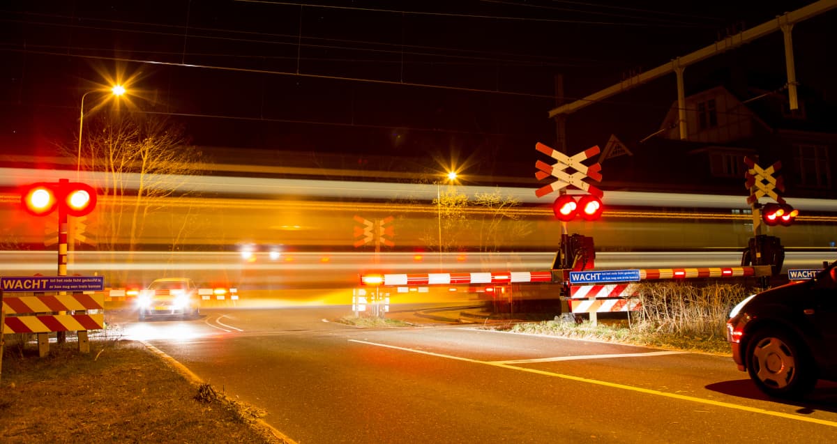
What is a boom barrier machine?
A boom barrier machine is the powered drive that raises and lowers the boom across the roadway at a level crossing. On a lower the motor and gearbox drive the boom down until it is across the road; on a raise it drives the boom back up against a counterweight until it is upright and held clear. The mechanism is deliberately rugged: an electric motor, a reduction gearbox, a counterweight that offsets most of the arm, and a snubbing damper that controls descent speed. The boom itself is a lightweight fibreglass or aluminium arm carrying red LED lamps and high-visibility retroreflective markings, designed to break rather than impale if a vehicle drives into it.
For monitoring, the piece that matters most is the proving. The crossing controller drives each boom and proves its position through relays — a boom is proved up or proved down — and those relay contacts are what a monitoring system reads. Most road crossings have a boom on each side of the road, so there are two booms whose proving states should move together. The relationship between those two states, and their timing against the rest of the crossing sequence, is the foundation of boom fault detection.
How boom monitoring actually works
The core technique needs no current measurement. The monitoring system reads the boom proving relays as digital inputs — volt-free contacts wired into the site data logger or RTU — alongside the crossing's other state inputs, principally the crossing-active condition and the lights. From just those relay states and the times at which they change, three things are continuously checked:
- Boom state — is each boom proved up or proved down, and is that correct for the current crossing condition.
- Sequence between the two booms — both booms should be in the same state; one up while the other is down means a single boom is stuck or slow.
- Timing against the lights — the booms should begin to lower a set interval after the lights start, and should be proved down before the train reaches the crossing; the relay transition times are checked against that expected sequence.
Because it works entirely from proving relays and time, this approach catches the operationally important boom faults at any crossing that has boom proving wired back to the logger — no current clamp, no analog input, and no modification to the vital circuit.
The crossing sequence
Boom timing only means something in the context of the whole crossing sequence. A normal activation runs in order: a train is detected on the approach, the lights start flashing and the bell sounds, then after a deliberate delay the booms lower and prove down, the train passes, and once the crossing clears the booms raise and the lights stop. Monitoring the booms means checking that their proving transitions fall in the right place in that sequence and within the expected times — that they start lowering within the window after the lights begin, that both reach proved-down together, and that they raise and prove up after the crossing goes inactive.
Core boom alarms (no current required)
The following alarms are derived purely from the boom proving relays and the crossing state. They are the heart of boom monitoring and apply at every crossing with booms, each mapped to a severity in the operations console and relayed to the central platform with SMS fallback when cellular comms are unavailable.
| Alarm | Condition |
|---|---|
| Booms Out of Sequence | The two booms are in different states when they should match — one proving down while the other proves up |
| Boom Fault | No booms proved down when the crossing is active, or booms proved down when the crossing is not active |
| Boom Delay (Lowering) | A boom takes longer than its expected time to prove down after the lower |
| Boom Delay (Raising) | A boom takes longer than its expected time to prove up after the crossing clears |
| Boom Sequence / Timing Error | Booms move out of order relative to the lights — lowering before the lights start, or not starting to lower within the expected window |
The distinction between a delay and a fault matters. A boom delay is a warning: the boom still completes its travel, just slower than its learned or configured time, which is the early, machine-readable sign of mechanical decline — a stiffening gearbox, a worn damper, a counterbalance drifting out of adjustment. A boom fault is the boom in the wrong state for the crossing condition, which is an immediate operational problem. Trending the lowering and raising times turns the first into a scheduled maintenance visit before it becomes the second.
Tip: Trend boom lowering and raising time per boom as a rolling 30-day view. Booms lower differently than they raise — one is assisted by the counterweight, the other works against it — and the two booms at a crossing can wear at different rates, so comparing both directions and both booms is the fastest way to spot a developing fault long before it trips a delay or sequence alarm.
Boom light faults
Booms carry their own red LED lamps that flash when the boom is lowered, and these can be monitored for lamp-out faults — but with an important wiring caveat. Detecting a failed boom lamp requires a current loop dedicated to the boom lights. Where the boom lights are wired on their own circuit, the same approach used for the main crossing flashers applies: a learning, current-sensing algorithm that counts the lit lamps and alarms when one drops out. That technique is covered in detail in our guide to level crossing flasher fault detection.
The caveat is that many crossings wire all the lights — the main approach flashers and the boom lamps — onto a single circuit. Where that is the case, the boom lights cannot be isolated and resolved on their own, so boom-lamp monitoring is only available when the boom lights have their own dedicated loop. It is worth confirming the lighting wiring at survey time, because it determines whether per-boom lamp monitoring is possible at all.
Pedestrian gates and mazes
Many level crossings include pedestrian protection — a set of pedestrian gates or a maze that guides people across. Where these are motorised, they close when the crossing is active in much the same way a boom lowers, and they can be monitored on exactly the same principle: their proving state, the sequence between gates, and their timing against the crossing condition. They raise the same family of alarms — out of sequence, gate fault, and gate delay — from the same kind of relay inputs.
Crucially, the road booms and the pedestrian gates are independent features. Some crossings have only pedestrian gates and no road crossing at all, in which case the pedestrian gates are monitored in their own right with no road-boom alarms.
Optional: boom motor-current monitoring
Motor current is an additional capability rather than the basis of boom monitoring. Where it is wanted, a split-core current clamp (a current transformer) is closed around the barrier machine's motor supply conductor in the location case and landed on an analog input of the data logger. That lets the system capture the drive-current signature of each operation and trend lowering and raising current over time, and the history is retained for condition-based maintenance — a raised running current points to rising friction, a current held high to an over-current trip points to an obstruction or strike, and an unusually light run can indicate a broken boom.
It is a genuinely useful layer, but it is optional and comes at the cost of a current clamp and an analog channel per machine. The relay-based out-of-sequence, boom-fault, and boom-delay alarms above do the operational heavy lifting without it, so current monitoring is best treated as an enhancement to add where the extra diagnostic depth justifies the instrumentation, not as a prerequisite for monitoring booms at all.
What to monitor in practice
For a complete boom and gate monitoring program, instrument the following at each crossing, enabling only the items that physically exist at the site:
| Signal | Purpose |
|---|---|
| Boom proving (up / down) per boom | The primary input — boom state and the basis of every core alarm |
| Sequence between the two booms | Detect a single stuck or slow boom (out of sequence) |
| Crossing-active and lights state | Correlate boom timing against the warning sequence |
| Boom travel timing | Lowering and raising duration from the proving transitions, for delay alarms and trends |
| Boom light current loop (if separately wired) | Per-boom lamp-out detection, flasher-style |
| Pedestrian gate / maze proving (if fitted) | Same state, sequence, and timing checks as booms |
| Boom motor current (optional) | Drive-current signature and trends for condition-based maintenance |
| Cabinet door / tamper | Security, change-of-state log |
Configured to the crossing
No two crossings are wired the same, so boom monitoring is enabled to match what is physically present. A crossing with no booms — flashing lights only — raises no boom alarms; the feature is simply not enabled. A crossing with only pedestrian gates monitors those gates and has no road-boom alarms. And boom-lamp monitoring is available only where the boom lights have a dedicated current loop. Matching the configuration to the asset is what keeps the alarm set meaningful and free of nuisance alarms for equipment that isn't there.
Why early detection matters
A boom barrier that fails to lower at a public level crossing is not just a delay — it removes or degrades the crossing's protection until a technician attends, and it puts a safety-critical asset that the public relies on into an unproven state. Standards frameworks such as EN 50126 (RAMS) and the road-rail interface rules built on documents like AS 1742.7 push operators toward demonstrable, condition-based upkeep of crossing equipment rather than purely periodic inspection. Watching the boom proving relays, their sequence, and their timing is the most direct way to satisfy that: it surfaces an out-of-sequence or slow boom before it becomes a failure to lower, and it converts an expensive, reactive failure into a cheap, scheduled adjustment.
Across a fleet of crossings the economics compound. A modest reduction in barrier-caused failures and the road and rail delay they trigger is, for most operators, one of the highest-value outcomes condition monitoring can deliver.
Frequently asked questions
How is a boom gate monitored at a level crossing?
Primarily from the boom proving relays, read as digital inputs at the site data logger. The system watches each boom's up/down state, the sequence between the two booms (they should agree), and the timing of those state changes against the crossing lights and the active condition. Motor current can be added as an optional layer, but it is not required for the core boom alarms.
What is a "booms out of sequence" alarm?
It is raised when the two booms are in different states when they should match — one boom proving down while the other still proves up. It points to a single boom that is stuck, slow, or has a drive, linkage, or proving-relay fault, and it is detected purely from the boom proving inputs.
What is a boom fault alarm?
The booms are in the wrong state for the crossing condition: no booms proved down when the crossing is active and should be protected, or booms proved down when the crossing is not active. Both are found by comparing the boom proving relays against the crossing-active state.
What is a boom delay alarm?
A warning that a boom is taking too long to go up or down, measured from the command or crossing state change to the proving relay reaching its new position. A boom that still completes its travel but is slower than expected triggers the delay warning — an early sign of mechanical decline ahead of an outright failure to lower or raise.
Can boom lights be monitored for faults?
Yes, but only if the boom lights are on a current loop separate from the main crossing flashers. Where they are, the same lamp-out detection used for the flashers applies. Where all lights share a single circuit, the boom lights cannot be isolated and resolved on their own.
How are pedestrian gates and mazes monitored?
Where pedestrian gates or a maze are motorised, they close when the crossing is active like a boom, and are monitored the same way — proving state, sequence, and timing — with the same out-of-sequence, fault, and delay alarms. Some crossings have only pedestrian gates and no road booms.
Is boom motor current monitored as well?
It can be, as an optional extra. A current clamp around the motor supply captures the drive-current signature and trends descent and rise current for condition-based maintenance, retained over time. But it needs a clamp and analog input per machine and isn't required for the relay-based core alarms.
Do all level crossings have booms?
No. The boom feature is enabled only where booms are fitted. Some crossings have flashing lights only and no booms; others have pedestrian gates but no road crossing. The monitoring is configured to match what is physically present at each site.
Boom and gate monitoring, out of the box
RailNet Operations ships with boom proving, sequence, and timing alarms — out-of-sequence, boom fault, and boom delay — plus pedestrian-gate monitoring and optional motor-current capture, as part of a wider level crossing monitoring suite. Preinstalled, IEC 61131-3 compatible, and integrated with a centralised operations console.
Request Information